Avionics Engineering Center Equipment
Avionics Engineering Center Equipment
From our flying laboratories to our ground-based technologies, the Avionics Engineering Center at Ohio University maintains a state-of-the-art fleet of technical equipment, including aircraft, an antenna anechoic chamber, and a suite of software for analysis and modeling.
Avionics Aircraft
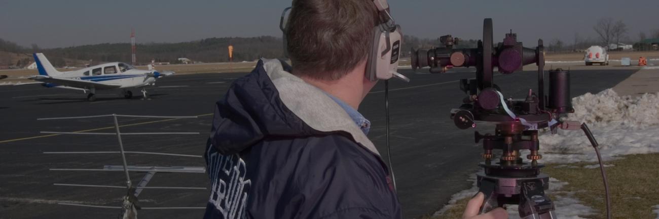
The Avionics Engineering Center operates a fleet of single-engine piston, multi-engine turboprop, multi-engine radial, and jet aircraft for transportation and research. In addition, we own and operate a Brumby unmanned aerial vehicle (UAV) housed, along with our manned fleet, in the Avionics Engineering Center hangar at the Ohio University Bush Airport in Albany, OH. We keep an FAA-certified Airframe and Powerplant mechanic with Inspection Authorization on staff to perform all necessary aircraft maintenance, repairs, and alterations, and to fabricate and install specialized equipment for research missions.
Read more information and technical specifications about our aircraft.
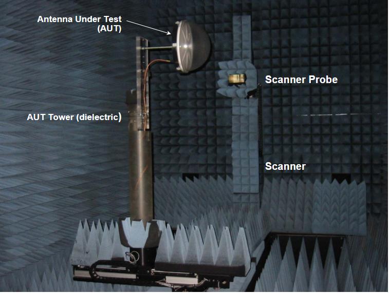
Antenna Anechoic Chamber
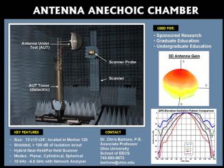
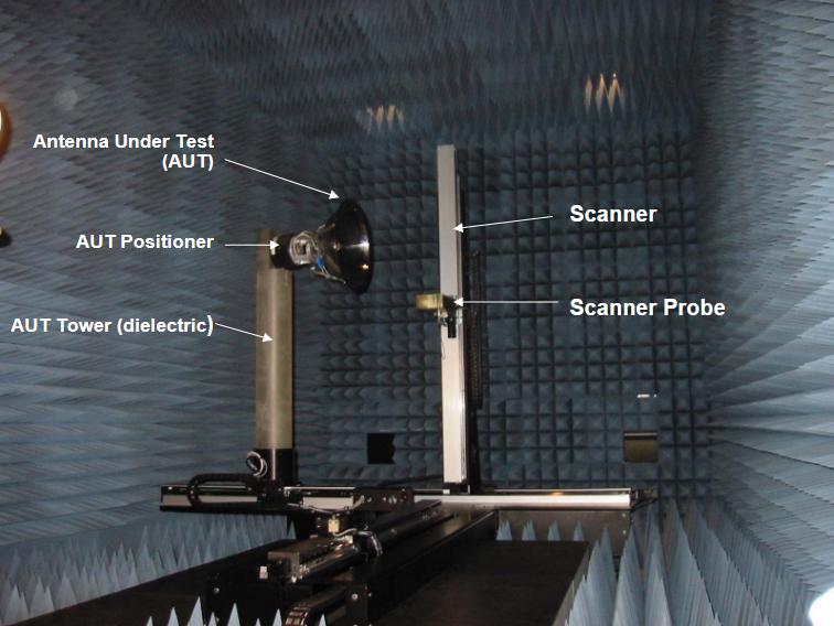
Our indoor Antenna Anechoic Chamber allows researchers to launch and verify in-house antenna designs for near-field and far-field measurements on electrical antennae. Enclosed by shielded anechoic technology, the antenna chamber provides added data accuracy and integrity, including more than 100 dB of isolation (104 dB @ 3GHz); planar, cylindrical, and spherical test modes; and a range of 10 kHz - 6.0 GHz with a vector network analyzer.
For more info, contact Professor Chris Bartone at 740.593.9573.
Chamber video (.mpeg)
Design Goals
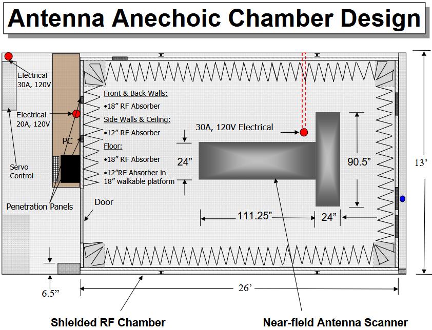
Use for: » Sponsored research » Graduate Education » Undergraduate Education • Indoor Antenna Range for easy of use and efficiency • Near-field Scanner for electrically large antennas » System can still be used for far-field measurement for electrically small antennas • Shielded Chamber for data integrity » Useful for some Electromagnetic Interference Compatibility Testing • Anechoic Chamber for data accuracy and validity • Establish within existing University Facility.
Antenna Anechoic Chamber (First Test: EE495 Senior Design: Spring 2003
- 13’x13’x26’
- Shielded
- 6 ft x 6 ft x 6 ft Scanner
- 7-Axis
- Hybrid Scanner » Planar » Spherical » Cylindrical
- AUT positioner removed for direct far-field
- Agilent 8753ES Based
- 10 kHz to 6 GHz
Typical Output Radiation Pattern Results
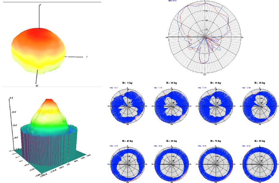
Antenna Anechoic Chamber-GPS Antenna
AUT positioner and walk-able surface removed
Typical GPS L1 Elevation Radiation Patterns
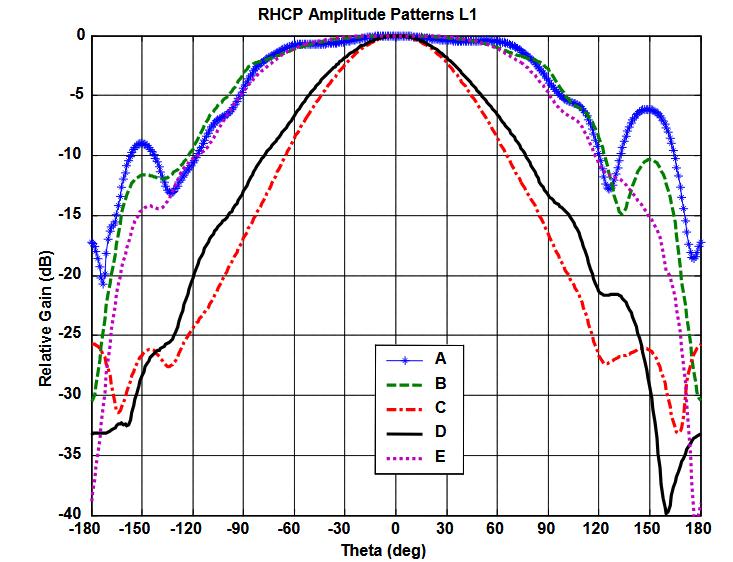
Anechoic Chamber Anti-jam Antenna Testing
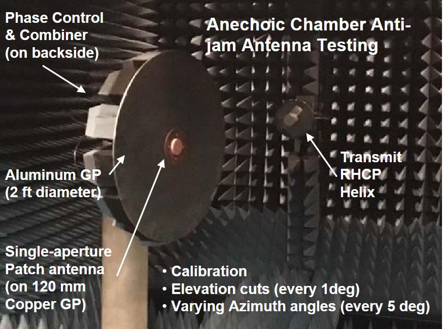
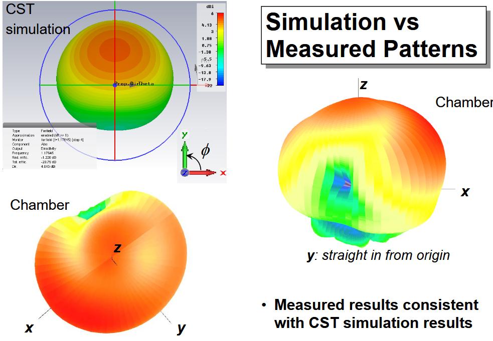
Simulated vs. Measured Patterns
Summary
- Initial Operational Capability as of 28 May 2003
- Indoor Antenna Anechoic Chamber Provides a new capability to launch and verify in-house antenna designs
- System can be used for both near-field and far-field measurements for electrical large and small antennas, respectively.
- Shielded Anechoic Chamber provides for added data accuracy and integrity. » RF Shielding alone provide for over 100 dB of isolation, (e.g., 104 dB @ 3GHz)
- Will be used for:
- Sponsored research
- Graduate Education
- Undergraduate Education