
The Ohio University Beam Swinger Facility
The Ohio University Beam Swinger Facility
Nuclear Instruments and Methods 198 (1982) 197-206 197
North-Holland Publishing Company
R.W. FINLAY, C.E. BRIENT, D.E. CARTER, A. MARCINKOWSKI **, S. MELLEMA, G. RANDERS-PEHRSON and J. RAPAPORT
Physics Department, Ohio University, Athens, Ohio 45701, U.S.A.
Received 21 December 1981
The Ohio University time-of-flight spectrometer has been completely redesigned to make use of a beam swinger magnet. Flight paths of 4-30 m are available over the angular range from -4° to + 160°. Improved shielding, collimation and detector design provide substantial improvements in neutron scattering experiments for neutron energies up to 26 MeV.
I. Introduction
For several years personnel at the Ohio University Accelerator Laboratory have been involved in the measurement of elastic and inelastic neutron scattering from a wide range of target nuclei between 1.2 and 26 MeV [1-3]. The excellent pulsed-beam characteristics of the Model T-11 tandem Van de Graaff accelerator have been an important asset in this program. Intense beams of negative 1H and 2H ions are produced with small energy spread in a tantalum hollow-cathode ion source. The transmission of the tandem is such that ~80 μA of deuterons and more than 100 μA of protons can be delivered on target in the direct current mode of operation. In the pulsed-beam mode, average beam currents of 3-5 μA of deuterons and 7-10 μA of protons can be focused on target in a burst of about 0.75 ns duration. The pulse repetition frequency is variable from 5 MHz to 78 kHz by factors of two.
Monoenergetic neutrons with 0 < En < 12 MeV are produced via the T(p,n)3He and the D(d, n)3He reaction. Between 20 and 26 MeV the T(d, n)4He reaction is used. The neutron-production target is a gas cell similar in design to that described by Carlson [4]. When deuterium target gas is used, the cell is operated at pressures up to 2.7 atm; with tritium gas the pressure is held under 1.6 atm. The entrance window may be either a Mo or a W foil of 5 μA thickness.
The pulsed neutron source and associated time-offlight spectrometer [1] has been used to measure nearly 400 differential cross sections for elastic and inelastic neutron scattering. Nonetheless, the existing system had important limitations particularly in the incident neutron energy region above 20 MeV. For example, the energy resolution of the spectrometer was limited by the maximum available flight path of 6.6 m. Moreover, the detector shielding was more appropriate for En < 10 MeV; consequently, the background in the region of the time-of-flight spectrum corresponding to about 8 MeV of excitation in heavy nuclei was too large to allow measurements in this region.
The availability of the Michigan State University beam swinger magnet [5] provided an opportunity to design a long-flight-path, high-resolution, low-background time-of-flight spectrometer for neutron scattering experiments.
2. The Beam Swinger
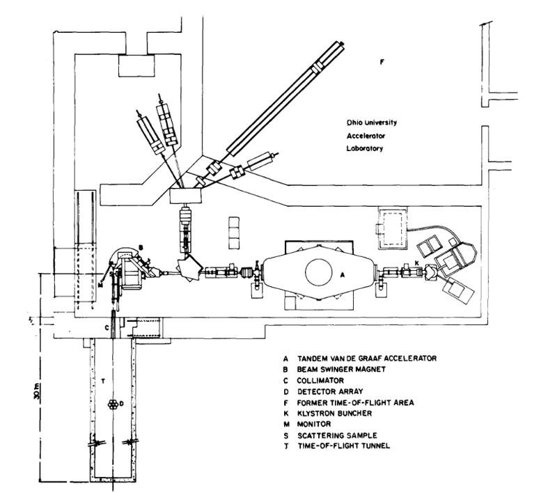
The physical properties of the Michigan State University beam swinger magnet have been described by Bhowmik et al. [5]. The swinger consists of two magnets which deflect the beam through -45 ° to + 135 ° respectively so that it emerges from the swinger perpendicular to the original beam direction. The magnets are double focussing (n -- ½) and the mass-energy product of about 52 is more than enough to accommodate the most energetic beam presently available from the Ohio University accelerator. The entire magnet is counterbalanced so that it may be easily rotated about the original beam direction to any angle between -4° and + 180°. The location of the beam swinger in the Ohio University laboratory is shown in fig. 1.
In order to obtain long flight paths with the new spectrometer, it was necessary to modify the accelerator building by the addition of the time-of-flight tunnel An inexpensive means of construction was adopted, namely 8 sections of precast concrete water conduit each 2.13 m in diameter and 3.35 m long were joined to the building at the location shown in fig. 1. An entry door and a 30 cm diameter collimator sleeve were built into the existing 1.22 m thick concrete building wall. The entire tunnel is buried under approximately 3 m of earth.
Location of the swinger magnet along the undeflected beam line of the tandem Van de Graaff accelerator has several consequences: The full intense-beam capability of the tandem is delivered to the entrance slits of the swinger with minimum transport loss. The beam is, however, unanalyzed; thus the -45° magnet of the swinger provides the beam analysis, and a set of control slits between the two swinger magnets provides feedback stabilization of the Van de Graaff terminal. Since the dispersion of the 45° magnet is rather small, precise determination of the accelerated beam energy is made with reference to a calibrated generating voltmeter. The precision power supply that is normally used for the beam switching magnet is available to energize the swinger magnet. The only significant change in the accelerator system that was required to accommodate the swinger was the replacement of the original magnetic quadrupole doublet lens at the high energy end of the tandem by a quadrupole triplet lens. Excellent vacuum is maintained in the swinger by means of a cryopump located between the -45° and + 135° magnets.
The problem of time-debunching in the swinger magnet is more important with the 4-9 MeV deuteron beam from the Tandem Van de Graaff than it was with the 20-45 MeV proton beam from the Michigan State University Cyclotron. Preliminary beam-optics calculations with the code TRANSPORT [6] indicated that, in the worst case, a debunching of 350 ps could be attributed to variations in deuteron paths through the beam swinger magnet. The actual beam burst duration was measured by observing particles elastically scattered from a thin gold foil with a fast scintillation counter. The stop pulse for the time-to-amplitude converter was derived from a capacitive pick-off unit. The measured burst duration was typically 550 to 800 ps both before and after the swinger magnet.
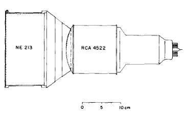
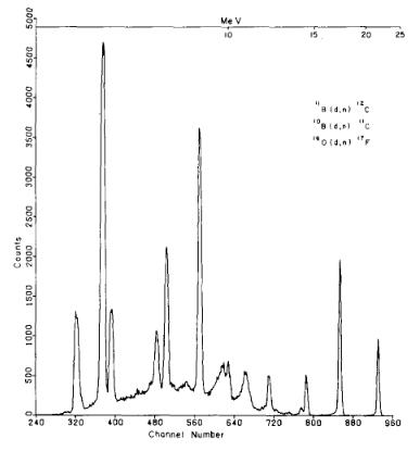
Fig. 3. Time-of-flight spectrum for neutrons produced in the natB(d, n) reaction at Ed =8 MeV, 0lab = 15°. The kinetic energy of several well-resolved neutron groups are shown. The peaks in channels 320 and 380 correspond to states in 17F which are populated by (d, n) reactions from a 160 contaminant on the target.
3. The Time-of-Flight Spectrometer
3.1. Design aims
The design aims for the new spectrometer can be summarized as follows: to improve the energy resolution in neutron scattering experiments while reducing the background and retaining or improving the counting rate. The more immediate aim was to improve the size, efficiency, and pulse-shape discrimination (PSD) qualities of the present detector system with initial operations to be carried out at a flight path of 13 m, i.e. twice the previously available flight path.
It should be emphasized that many factors contribute to the final energy resolution in a neutron scattering experiment. At long enough flight path, the energy spread in the neutron production reaction will result in a time uncertainty which is large compared to the time spread in the neutron detectors or electronics. In order to investigate these effects a computer program TOFSIM [7], was written to simulate the contribution to time resolution due to beam burst duration, beam straggling and energy loss in the source reaction gas cell, kinematical variations in the source and scattering reactions, detector thickness, etc. This code proved to be exceedingly useful in the evaluation of system performance and the design of neutron scattering experiments.
3.2. Neutron Detector Design and Performance
After consideration of the design of several large-area [8] and large-thickness [9] detectors, it was decided to construct an array of seven smaller more conventional detectors. The array consists of a central detector surrounded by an annular ring of six identical units (fig. l). Each of the detectors could then be designed for excellent timing and PSD properties, and the additional information provided by a subdivided array might be an advantage in the actual experiment. For example, in the forward direction where scattering cross sections are large and collimation is difficult, the central detector alone might be more useful than either a very large detector or a large array. Near deep minima in the elastic scattering cross section, the response of each member of the array can give detailed information on the shape and depth of the minima.
In order to take advantage of the excellent PSD properties of the organic liquid NE-213, scintillation cells were fabricated from aluminum tubing (18.8 cm inside diameter × 10.2 cm long) with a thin aluminum entrance window and a borosilicate glass observation window. The aluminum surfaces were painted with an epoxy-based TiO2 diffuse reflecting paint. The observation window was coupled to a 6 cm long tapered plexiglass light pipe that was cut to a spherical shape which matched the photocathode surface of an RCA-4522 photomultiplier tube. The sides of the light pipe were partially painted with diffuse reflecting paint as suggested by Schrlermann and Klein [10] in order to reduce the dependence of the anode pulse height on position of the event within the scintillator volume. Details of an individual detector are given in fig. 2. The total sensitive volume of the seven-detector array is 20 I.
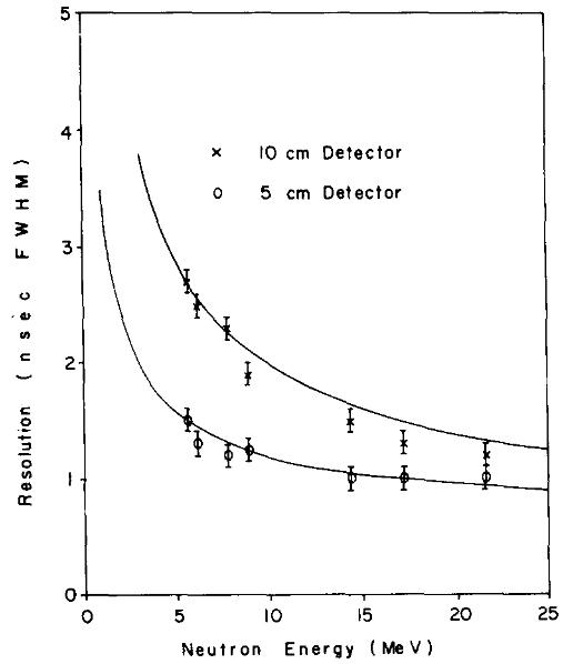
In order to test the response of this detector to neutrons in the energy region of interest, the natB(d, n) reaction was studied at Ed = 8 MeV. Energy or time spread due to kinematic factors and target size or thickness were minimized so that time resolution should be determined by only two factors: beam burst duration and time response of the detector-including electronics. A typical spectrum with the 10 cm thick detector biased low enough to detect 5 MeV neutrons with good efficiency is shown in fig. 3. Similar spectra were obtained for a variety of scintillator dimensions and a range of detector biases. In fig. 4 the time resolution Δt in ns, full width at half-maximum (fwhm) is plotted for seven well-resolved peaks both for the present detector and for a 11.5 cm diameter × 5 cm thick commercial detector [ 11 ]. The solid lines are the expected resolution as a function of neutron energy according to the program TOFSIM. As expected the time width of the peak increases with decreasing neutron energy due to the increasing importance of flight path uncertainty i.e. scintillator thickness. The energy width of the peaks is approximately constant at ΔE ≅ 0.01E. It may be significant that the performance of the 10 cm detector is rather better than anticipated at the highest energies measured. The program TOFSIM explicitly calculates the difference between neutron and photon transit time across the sensitive volume and combines this uncertainty in quadrature with the beam burst duration. This procedure apparently overestimates the actual time resolution of thick detectors at high energy. A similar effect was reported by Watson et al. [12] who attribute it to an increase in average transit time of photons to the cathode from events which take place far from the photocathode. The photons from such events are more likely, on the average, to have undergone multiple reflections from the diffuse-reflecting paint. Of more striking importance is the observation from fig. 4 that for En > 16 MeV relatively little is lost in the time resolution when the scintillator volume is increased fivefold.
The program TOFSIM does not include any parameterization of timing errors in the electronics (e.g. "walk"). The combination of very high quality constant-fraction timing discriminators and a novel treatment of the photomultiplier bias chain seems to render this contribution negligible over the time scales and dynamic ranges of interest in this work. The new biasing system [13] attempts to deal with the problem of anode current saturation for large energy deposition in the scintillator, Anode current linearity is essential if the constant-fraction timing principle is to be used; dynode linearity is equally vital for PSD. With many standard bias resistor chains, linearity can only be preserved by reducing the overall tube voltage. This remedy has the undesirable effect of reducing voltage gradient for the first few stages and thus increasing transit time dispersion at the photomultiplier anode. The new system meets the requirement of high electric field near the cathode (for timing) and a large range of linear anode currents (for timing and pulse shape analysis).
3.3. System Electronics
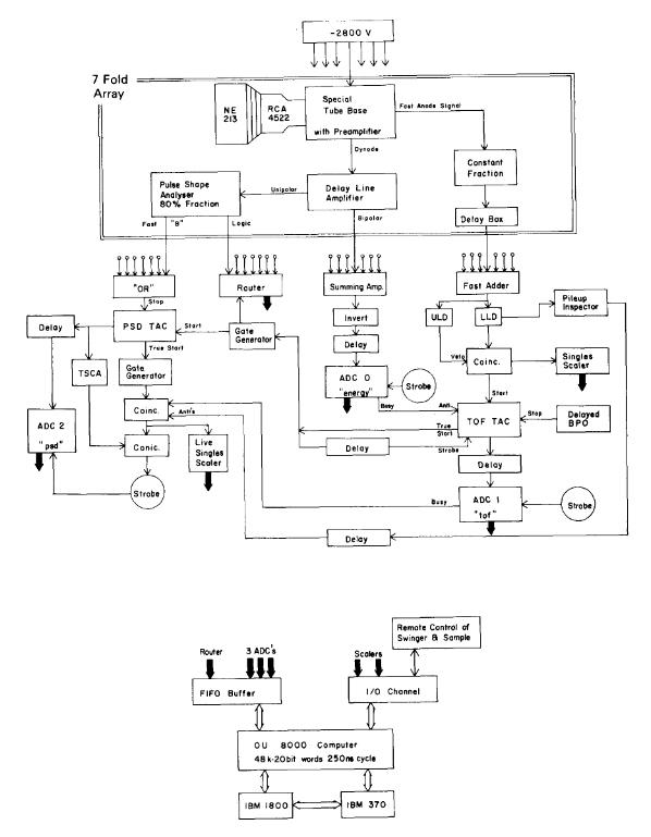
The overall block diagram for the seven-detector array is shown in fig. 5. The basic design philosophy was to fan in the timing information at an early stage but to treat the linear (pulse height and shape) information for each photomultiplier separately until after the neutronor-gamma-ray decision is made. Better separation of neutron and gamma pulses is obtained by this approach since the noises on the seven linear signals are never added. The logic or TOF information from the seven detectors, however, is processed by a single time-to-amplitude converter and a single analog-to-digital converter. Thus, there is only one time scale for the entire array. The outputs of the seven constant fraction discriminators may be delayed in steps of 1/8 ns until the time-of-flight spectra from the several detectors coincide. Routing pulses are derived from the dynode signals of each detector so that the on-line data acquisition system [14] can store both the separate response (timeof-flight, energy and PSD) of each detector and the combined response of the array.
The principle of dynamic biasing [15] of the neutron detector has been applied to the system so that the detector efficiency can be kept as large as possible over a wide range of neutron energies. The parameters of the dynamic biasing are established as follows: For a given beam pulse repetition period τ0 (variable from 200 ns to 64X 200 ns by factors of two) the neutron energy corresponding to 2τ0 plus the time of flight of the highest energy neutron of interest is determined. All hardware discriminator thresholds are set near to but below this value. Pulse height signals from the dynodes are applied to ADC-0 while time of flight goes to ADC-1. The computer tests the pulse height against a table of 64 upper- and 64 lower-level discriminators depending on the time-of-flight channel number. If the discriminators are satisfied, the time-of-flight event is stored. The upper level discriminator is set to the maximum pulse height for that neutron energy, and hence, decreases as neutron time of flight increases. The lower level discriminator levels also decrease as neutron time of flight increases but are always set high enough to eliminate very slow neutrons from the previous beam bunch which have flight times equal to the % plus the fight time of the event of interest. The shapes of the upper and lower bias curves are calculated from a single-power-law fit to the proton light output data of Verbinski et al. [16] for NE213.
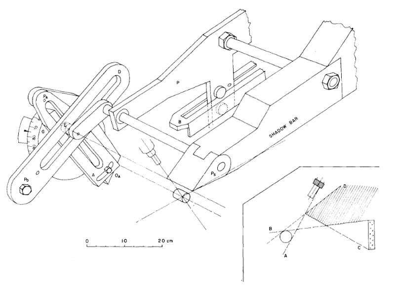
Fig. 6. Mechanical arrangement for the self-positioning shadow bar. Criteria for the proper placement of the shadow bar are shown in the insert. The shadow bar consists of CH2 and Cu with maximum length 140 cm, width 9.5 cm and height 21 cm. The first 45 cm at the front of the shadow bar are pure Cu. The shadow bar is suspended from an aluminum plate, P, and counter balanced with a lead weight (not shown) so that it rolls smoothly on a floor-mounted steel bar B. The angle that the bar B makes with the floor is easily adjusted so that criterion B (insert) is satisfied. As the swinger magnet is rotated, the goniometer circle G and the slot A rotate. Slot D is stationary. Motion of the double bearing E within these slots controls the motion of the shadow bar as follows: Motion of the inner bearing E within the slot A guarantees that the tip of the shadow bar moves along the criterion line A. The pivot point of slot A, PA, can be raised or lowered to accommodate a range of source-to-sample distances between 9 and 20 cm. The orientation of A can be adjusted at OA to allow for a range of sample diameters between 1 and 4 cm. The role of slot D is to provide for a slight rotation of the tip of the shadow bar about the axis Ps so that criteria C and D cannot be violated. The vertical position of the pivot point, PD, determines the location of the shadow bar tip along criterion line A. The orientation of slot D affects the rate of rotation of the shadow bar tip and must also be adjusted according to sample diameter. This system provides fully automatic positioning of the shadow bar over a maximum range of 0° to 148°.
4. Application to Neutron Scattering
The application of the basic beam swinger magnet and time-of-flight spectrometer to neutron scattering involves several important considerations which would not be present if the system were limited to the study of neutron producing reactions such as (p, n) or (3He, n) reactions. Most important among these considerations are (a) collimation and shadowing of the neutron source, (b) scattering sample position, and (c) the introduction of additional sources of time spread.
4.1. Collimation and Shielding
The collimator sleeve that connects the accelerator vault and beam swinger to the time-of-flight tunnel (fig. l) provides both limitations and opportunities. The maximum solid angle that can be subtended by a detector located just inside the tunnel is 5.5 msr (Δθ = -+ 2.4°). In practice, this is not an important limitation since it is usually necessary to measure differential elastic scattering cross section with somewhat smaller angular acceptance. Thus, a series of tapered polyethylene collimator liners was constructed to fit the wall sleeve and provide the desired angular acceptance. The choice of polyethylene for the collimator of high-energy neutrons is at variance with the conventional wisdom but seems to be clearly indicated, at least up to 15 MeV, by the detailed Monte Carlo simulations of collimator performance by Schlegel-Bickmann et al. [17]. Since ample space was available between the source location and the nearest possible detector position, the tapered CH 2 collimator could be made quite long i.e. 230 cm. A second set of CH z collimators was constructed to fit inside the first set to provide an even smaller collimated solid angle. The dimensions of the optional inner collimator were chosen to subtend either the central detector of the 7-fold array at the standard flight path or the entire array at the maximum available flight path.
The performance of the shadow bar is crucial in neutron scattering experiments. Its role is to shield the detector and the collimator throat from the direct source neutrons. At the same time it should not become a secondary source that emits neutrons in the direction of the detector or the scattering sample. In the present geometry, the neutron detector array has no local shielding so all of the background reduction techniques must operate close to the neutron source.
Criteria for the proper placement of a shadow bar in a neutron scattering experiment have been described by Hopkins et al. [18]. In fig. 6 (insert) their criteria are illustrated with slight modifications appropriate to the swinger geometry. Criterion A requires that the point of the shadow bar should lie along a line tangent to the scattering sample and through the edge of the neutron production target. Criterion B requires that the long surface of the shadow bar lie along the tangent line between the top surface of the scattering sample and the uppermost point of the detector array. The dashed lines C and D in fig. 6 illustrate the additional requirements that the face of the shadow bar nearest the scattering sample not be viewed by any point on the detector array and that the face of the shadow bar nearest the gas cell not be viewed by the scattering sample. These criteria can be met over a wide angular range provided that the tip of the shadow bar is free to rotate.
Hopkins et al. proposed a mechanical assembly of bearings and plates which constrained the shadow bar to move in accordance with the criteria automatically as the neutron detector was rotated in the horizontal plane. The mechanical problem in the swinger geometry is to construct a similar series of constraints which would operate in the vertical plane. In the swinger geometry it is particularly valuable to achieve automatic positioning of the shadow bar since the other mechanical parameters of the experiment - swinger angle and sample position - are operated remotely under computer control. A very satisfactory solution to this problem is illustrated schematically in fig. 6.
As illustrated, the tip of the shadow bar is quite thin so that it will fit into the small space between the magnet pole and the scattered-neutron flight path at large scattering angle. Beyond 148° the shadow bar is decoupled at the bearing E and retracted as much as necessary to permit the measurement. The thickness of the shadow bar is consequently too small when the swinger magnet is rotated for measurements at smaller scattering angle. Present practice is to augment the front end of the shadow bar with an additional thickness of Cu for use at the forward scattering angles and to remove these Cu blocks for angles greater than about 120 °. If the present system has one failing it is that the attenuation of the Cu is not as large as is desirable for En > 20 MeV. There is not sufficient space to contain a much more massive shadow bar which still meets all of the placement criteria over a large angular range. It is occasionally necessary to employ ad hoc modifications in order to improve a particular region of the time-offlight spectrum. Replacement of the Cu by the more effective but more expensive element W is under consideration.
4.2. Scattering Sample Geometry
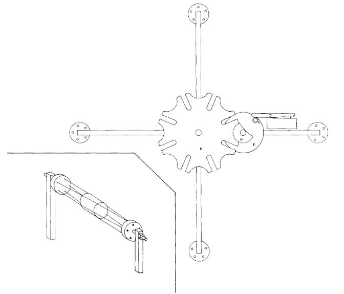
Scattering samples for neutron scattering experiments are normally right circular cylinders. In the beam swinger geometry, the axis of the cylinder is in the horizontal plane. Since neutron scattering by the air in the vicinity of the scattering sample is a principal source of background, a typical measurement at each angle consists of both a "sample-in" and a "sample-out" measurement. Thus it is desirable to remove and replace the scattering sample quickly, accurately and remotely. In the present system, these requirements are met by using a "Geneva Drive" mechanism which rotates a sample holder very accurately through 45°. The sample holder and drive are illustrated in fig. 7. Samples are suspended between the arms of the sample holder in a nest of fine nylon strings. The sample holder can accommodate three samples and one empty nest position for sample-out measurements.
Good collimation of the air space around the sample is best achieved for cylinders with length and diameter equal to about 2 cm. Isotopically enriched samples are not always available in these dimensions, so some flexibility is built into the shadow bar and collimator to accommodate a range of sample dimensions. The collimator is adjusted simply by sliding the CH2 pieces toward or away from the sample. The shadow bar adjustment was described in fig. 6.
4. 3. Determination of Zero Degrees
Since the differential elastic scattering cross section is often characterized by deep diffraction minima, it is important to know precisely the scattering angle and, in particular, to determine the true zero of the angular scale. In the previous system it was always possible to map the source flux or measure the scattering cross section at negative angles. With the swinger magnet the largest accessible negative angle is -4° and the anisotropy of the source reaction is small enough that a precise location of zero degrees is difficult.
A simple but elegant determination of zero degrees in the source reaction is possible. A small quantity of oxygen is admitted to the gas cell and the 160(d, n0)17Fg.s, and 160(d, n1)19Fist reactions are studied in small steps from -4° to +4°. The excited state transition proceeds via l = 0 transfer and the ground state transition has l-transfer = 2 [19]. The ratio of the ground state transition to the excited state transition has a sharp maximum at θ = 0°. The experiment requires no monitor or charge integration and provides a reliable determination of zero in the source reaction to within ±0.05°.
It remains then to show that the scattering sample has been placed symmetrically in the zero-degree flux. This is done by performing a transmission experiment between -4° and +4° . The transmission minimum at zero degrees is sharp enough to permit the location of the true zero in the scattering experiment to within ±0.1º. The precision of the standard optical alignment technique was confirmed.
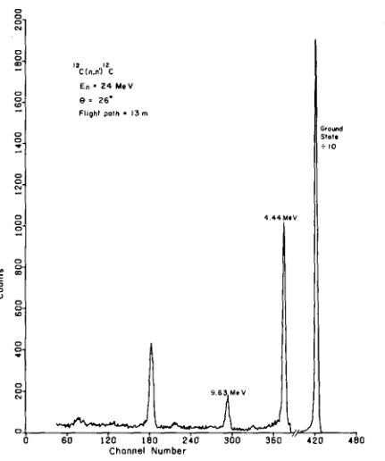

Fig. 9. Laboratory differential cross sections for 7.2 MeV neutrons scattering elastically and inelastically from 208Pb. Relative errors are indicated only when they exceed the size of the plotting symbol. The data have not been corrected for multiple scattering.
5. Results
Neutrons with kinetic energy of (24.0±0.06) MeV were produced by bombarding a 3 cm long gas cell filled with 1.5 atm of tritium gas with 7.07 MeV deuterons. The gas cell has a 5 μm thick Mo entrance foil and a gold beam stop. Neutrons elastically and inelastically scattered through 26° by a 15.5 g carbon scattering sample are detected in the 7-detector array at a flight path of 13m. The raw sample-in spectrum in fig. 8 shows clear evidence of the ground state and the excited 2+ and 3- states at 4.44 and 9.63 MeV. The much weaker 0+ state at 7.6 MeV and 1+ state at 12.71 MeV are discernable in fig. 8 and are distinct in a background-subtracted spectrum. The large peak near channel 180 corresponds to elastic scattering of 10.2 MeV neutrons produced by the parasitic 2H(d, n) reaction in the tritium gas cell. When the spectrum in fig. 8 is compared with similar (unpublished) spectra taken in this laboratory with the old spectrometer, the most striking difference is in the reduction of background (about two orders of magnitude) in the sample-in spectrum in the region of the 9.63 MeV peak.
The largest contribution to the energy or time resolution under these conditions is the straggling and energy loss of the deuteron beam in the entrance foil and target gas which amounts to 1.9 and 2.0 ns for the ground and first excited states, respectively. Contributions from the detector response and kinematic variation of neutron energy with scattering angle are also present but smaller. The actual performance of the spectrometer is somewhat better than the predictions of TOFSIM (2.2 and 2.6 ns for these peaks). The difference appears to lie in the treatment of kinematic energy spread which increases monotonically from 0° to near 90° and is an important effect in the scattering from light nuclei. Its importance can be reduced in the present circumstances by performing the final time alignment of the seven-detector array with neutrons scattered from carbon through 45°. In this manner, the coherent contributions to line width across the finite dimensions of the detector array can be made to cancel out. Used in this manner, the multi-detector array can be thought of as a "time-loss spectrometer" — the analog of the "energy-loss spectrometer" in charged-particle physics [20].
In the first experiment which employed the entire system described above, 7.22 MeV neutrons were scattered from a 109 g sample of 208Pb. Measurements were taken every 4° (2° at the forward angles and near the elastic minima) between 8° and 160°. Differential cross sections in the laboratory system are shown in fig. 9 for the ground state and 3- state at 2.63 MeV. The data have not been corrected for multiple scattering and are shown only to indicate the range and precision of neutron scattering measurements which are possible with the beam swinger technique.
The authors wish to acknowledge the generosity and cooperation of the staff of the Michigan State University Cyclotron Laboratory, especially A. Galonsky and S.M. Austin for making available the beam swinger magnet and the Geneva Drive mechanism. We also wish to thank F.S. Dietrich for his interest and assistance in measuring neutron scattering from Pb and in the zerodegree determination. The mechanical insights and skills of P. Beasley, R. Smith and D. Sturbois of the Physics Department contributed much of the final development of the spectrometer. The meticulous work of B. Hohon, R.G. Kurup and A.S. Meigooni in painting and preparing the detectors was largely responsible for the excellent performance of these units.
References
[1] J. Rapaport, M. Mirzaa, H. Hadizadeh, D.E. Bainum and R.W. Finlay, Nucl. Phys. A341 (1980) 56.
[2] D.E. Bainum, R.W. Finlay, J. Rapaport, J.D. Carlson and W.G. Love, Phys. Rev. C16 (1977) 1377.
[3] R.M. White, R.O. Lane, H.D. Knox and J.M, Cox, Nucl. Phys. A340 (1980) 13.
[4] J.D. Carlson, Nucl. Instr. and Meth. 113 (1973) 541.
[5] R.K. Bhowmik, R.R. Doering, L.E. Young, S.M. Austin, A. Galonsky and S.D. Schery, Nucl. Instr. and Meth. 143 (1977) 63.
[6] K.L. Brown, D.C. Carey and C. Iselin, SLAC Report No. 91 Rev. 2 (1977).
[7] S. Mellema, R. Finlay, G. Randers-Pehrson and S. Graham, Bull. Amer. Phys. Soc.
[8] C.D. Goodman, D. Bainum, J. Rapaport and C.E. Brient, Nucl. Instr. and Meth. 151 (1978) 125.
[9] J.D. Carlson, R.W. Finlay and D.E. Bainum, Nucl. Instr. and Meth. 147 (1977) 353.
[10] H. Sch/51ermann and H. Klein, Nucl. Instr. and Meth. 169 (1980) 25.
[11] Model BA1, Nuclear Enterprises Corporation, Edinburgh, Scotland.
[12] J.W. Watson, F.3. Wilson, C.A. Miller and D.O. Wells, Nucl. Instr. and Meth. 164 (1979) 129.
[13] G. Randers-Pehrson, D.E. Carter and R.W. Finlay, to be published.
[14] D.E. Carter, Nucl. Instr. and Meth. 160 (1979) 165.
[15] J.D. Brandenberger and T.B. Grandy, Nucl. Instr. and Meth. 93 (1971) 495.
[16] V.V. Verbinski, W.R. Burrus, T.A. Love, W. Zorbel and N.W. Hill, Nucl. Instr. and Meth. 65 (1968) 8.
[17] D. Schlegel-Bickmann, G. Dietze and H. SchOlermann, Nucl. Instr. and Meth. 169 (1980) 517.
[18] J.C. Hopkins, J.T. Martin and J.D. Seagrave, Nucl. Instr. and Meth. 56 (1967) 175.
[19] S.T. Thornton, Nucl. Phys. A137 (1969) 531.
[20] B.L. Cohen, Rev. Sci. Instr. 30 (1959) 415.